Tuesday, April 14, 2015

Matlab 2


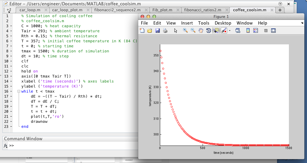
To further our understanding about MATLAB, we had to show a code that simulates how a cup of coffee cools to room temperature. The code and resulting graph. The graph plots time on the x axis and the temperature of the coffee on the y axis. Note all temperature is in Kelvin.

Question 1: How does the cooling behavior change if we vary the parameters Rth (thermal resistance) and C (heat capacity)?

 If you increase Rth and C, the coffee will retain more heat and the graph will decrease slower and the coffee will stay hot longer.
Rth increased from .8 to 2.85 while C stayed the same.

Rth stayed the same, while C increased from 1000 to 2000
Rth increased from .85 to 2.85 and C increased from 1000 to 2000
On the other hand, if C and Rth decrease, the coffee will not retain heat as well and the coffee will cool off much quicker.
Rth decreased from .85 to .15 while C stayed the same

Rth stayed the same, while C decreased from 1000 to 100

Rth decreased from .85 to .15 while C decreased from 1000 to 100

Then we needed to add a heater to the coffee. If the coffee started at room temperature and turn the heating element on, the element would add thermal energy to the system at a constant rate P.

Question 2: Calculate the value for P if we want our coffee to heat up to the Starbucks ideal of 84 degrees Celsius or 357 Kelvin?

P=75.29- We were given an equation in class and we then solved it to find this number

Once we found P, we needed to incorporate P into our program to see how it would affect the system. Over time, the coffee heated up to the desired temperature.


Then, we needed to modify the program to simulate a temperature controller that uses bang-bang control to reach and maintain the desired temperature.


Below is a zoomed in version of the graph.

Page 9. Question 1: Why is bang-bang control appropriate for many thermal systems? When might it be insufficient?

It is appropriate for thermal systems because it heats up to the desired temperature as fast as possible and is also cheap and easy to implement. The reason why our proportional control heated up faster than our bang bang control was because the max power in our proportional control is a lot larger than our max power in our bang bang control. However, it could be insufficient if it would be detrimental if the temperature went above the desired temperature as bang-bang control will ends up going a small amount over the desired temperature.  

Then we needed to create a program that uses proportional control to reach and maintain the desired temperature.


Page 9. Question 2: How does this approach compare to bang-bang?

This approach never reaches the desired value, though it does get very close.

After, we assumed that there was a delay between the time the coffee reaches a given temperature and when the temperature sensor records that temperature. We needed to modify both of of our programs to include the affect of adding a "sensor delay".

Bang Bang Control
The impact of the sensor delay is that the temperature gets read 5 seconds after it was initially read. Because of the delay, the first 5 seconds of the graph show a temperature of 293. It also doesn't turn the power on as often since it records temperature of the coffee 5 seconds after it reads the temperature.

Proportional Delay

The sensor delay has the effect that the temperature gets recorded 5 seconds after it was initially read. Therefore, the first 5 seconds of the graph are at a temperature of 293. The temperature also goes over the desired temperature since it records the temperature 5 seconds after it has read it. Then the system will turn off the power after it has gone over the desired temperature by 5 seconds.

Question2: What other delay(s) might you expect in your thermodynamic system, apart from sensor delays? 

One other delay can be an action delay. There could be a delay when the power is supposed to turn on to when it actually turns on.

Reflection:
I completely understand bang bang and proportional control now. It took us a long time to do the last problem with the delay because of small syntax errors. So I know that it is important reread the code to fix all errors.


Friday, April 10, 2015

MATLAB Introduction

This week we started to learn MATLAB by reading the first chapters of Physical Modeling in MATLAB by Allen Downey and doing some exercises from the book.

The first exercise 2.1 was to translate the equation of the nth number of the fibonacci sequence in MATLAB.


2.3- calculate the number of cars in two locations, Boston and Albany, of a rental car company each week. Each week 5% of the cars in Albany are dropped off in Boston and 3% of the cars in Boston are dropped off in Albany. This script updates the number of cars in Boston and Albany each week. At the beginning of the year, 150 cars are at both locations.

Exercise 3:1- Use the for loop to run car.update 52 times. This would tell us how many cars will be in Boston and Albany at the end of the year. The year starts with 150 cars in Boston and 150 cars in Albany.

Exercise 3:2- We modified the car_loop so that it will plot the number of cars in Boston and Albany each week over time. The cars in Boston are in blue diamonds and the cars in Albany are in red circles.

Then, we started with there being 10000 cars in Albany and 10000 cars in Boston at the start of the year.

3:5- Compute the first ten digits of the fibonacci sequence using the recurrent equation. 


 Then, generalize the equation to compute the first n digits of the fibonacci sequence.

4.6- Write a script that computes a vector of the first n values of the Fibonacci sequence. Then compute a new vector that computes the ratio of consecutive values of the Fibonacci sequence. Plot the vector. The ratio of consecutive Fibonacci values seems to converge on about 1.6.


Friday, April 3, 2015

Arduino Part 3

ENCODER
We started using a sensor called an encoder that transmits how many times the shaft has rotated. The program will tell you how many times it has rotated in the serial monitor. The code for the encoder. The sciborg will move backward for 200 loops and then forward for 200 loops.
The starting value for the encoder is at 0 because at the start of every run, the sciborg hasn't gone anywhere. The ending value is also zero because the sciborg goes forward 200 turns goes in reverse for 200 turns. 200-200=0. However, the end value isn't always zero because inertia stops the sciborg from starting immediately. 

TOUCH SWITCH
The front of the sciborg has a touch switch that senses when it hits an obstacle. The switch is a lego button that you integrate into the sciborg using the breadboard. The touch switch program turns on a LED on the sciborg. However, the LED doesn't turn off because the code doesn't specify that it turns off.

Then we modified the code so that the light will only turn on when the button is pressed. 

ULTRASONIC SENSOR
An ultrasonic sensor can detect objects within a certain area. They use high frequency sound to detect and localize objects. They measure the time of flight for sound that has been transmitted to and back from nearby objects and use that to output a range reading. 

FEEDBACK AND CONTROL ACTIVITIES

Fixed distance, bang bang control
In a previous sketch we got the car to go 10 ft after a certain number of milliseconds. The first time we did it we only got about halfway to the finish line. However, by the end we were able to get within 2cm of the finish line every time that we let the motor go. We then needed to get the sciborg to move 10 feet using both the ultrasonic sensor and the touch sensor. We got exactly 10 feet with the touch sensor but only got within 5 cm with the ultrasonic sensor.

Ultrasonic Sensor
Touch Sensor


Fixed distance, proportional control
We wrote a sketch that uses proportional control to go exactly 10 feet using the encoder. As the sciborg got closer to the 10 feet mark, it went slower.
However, when we did this, the sciborg would stop a foot from the end because there was not enough power supplied to the motors to get to the end. So we made a code called nudge to add to the end of the proportional control so it would get to the end. Nudge causes our car to move a very small distance by very briefly turning on the motors at low power.

Nudge
Nudge on Proportional Control
This allowed our sciborg to get within a centimeter of the 10 foot mark every time

Conga Line
We needed to make a code so that our sciborg will follow something in front of it in a straight line. First using bang bang control, and then using proportional control.
Bang Bang Control
Conga Line Proportional
Both worked very well. The sciborg moved a lot more smoothly with proportional control than bang bang control. However we had a hard time making our sciborg run straight for all assignments.


Final Project

For our final project, we need to make something for children. Some of the things typically have problems with is that they want to wiggle and move instead of staying on their carpet square and it is hard for children to lock and unlock the bathroom doors. Some children also have a hard time remembering to take only one paper towel, flush the toilet, or wash their hands.


Possible Project Ideas:
1) Create a new carpet square so the children know when they are on the mat or not. This could be implemented by emitting a sound when children get off the square.
2)Create a mechanism that would make the bathroom toilets quieter or less scary when flushed. This could be implemented by having another song play over the sound of the toilet.
3)Create a system so children know how loud they are being in the room. This could be implemented by having a sound sensor hooked up with the lights. When the sound is too loud, the lights would turn off to create a more soothing environment for the children and to let them know they were too loud.
4)Create a mat to put under the water table or sand table so children know when water or sand is             hitting the floor.

Monday, March 16, 2015

Rob Wood Talk

On Thursday, I went to a talk by Rob Wood about Robobees, flying machines, about the size of a bee that can fly in the flight pattern of flies. So far, they have been able to make the Robobees get off the ground and land sideways on a surface. I thought that the most interesting part of the lecture was how they made the Robobees. At first, people would hand build the bees by using tweezers to put all the pieces on the body. This process was very time intensive and took a lot of skill to complete. Since they wanted to be doing a lot of experiments with the bees, the lab wanted a faster way to make the bees so they could make a lot of them in a short period of time. So, they took inspiration from pop up books and found a way to fold the bees into place. The process starts by machining different layers of material in a specific pattern.Then they stack the layers together and laminate them. After that they will release the device and pop the bee out of the flat, layered, piece into the Robobee. This process allows a 2 dimensional object to be made into a 3 dimensional object. This process can be used with any material, is fast to make, can make any structure, and allows different sensors to be put in while the bee is still flat. The downside to this process is that it takes a long time and is very difficult to design.

Saturday, March 14, 2015

Arduino Part 2

We got a new sensor, a photocell or light sensor. Before we could use it, however, we needed to calibrate the light sensor. The first photocell code had values for dark, dim, light, bright, and very bright set too high. Below is the changed values for how much light the photocell sees.


For our next project we got to use a light sensor, LED and a servo motor at once. When the light sensor sensed bright light, the LED would flash with a certain frequency. When the light sensed dimmer and dimmer light, the LED would flash with an increasingly smaller frequency and the servo motor would move to a different spot.

The Setup
The blue lego piece near the keyboard is the light sensor
The Code


The Video

It's hard to tell in the video, but as I take my hand away from the photocell, the servo motor moves to a slightly different position. 

On class on March 10, we got a new project set to start working with sciborgs. The first part of the project was learning how to make functions. We found out how to make an led flash SOS in Morse code using a function. A function allowed us to use less code and make writing the code much less repetitive. 


We then had to make part of our sciborg, which was fun! We needed to complete some of the installation and solder the batter pack together. Then we needed to work with the sciborg starting with a "single motor" sketch. This sketch allows one motor to run forward for a couple seconds, and then backward for a couple seconds.

Then we deleted all of the extraneous code which was all the code that wrote any words in the sketch. After, we added a second motor to the sketch so they both would run at the same speed. 

After that, we made both motors run at speed 0 and 1. The wheels would not turn at that speed because there wasn't enough power diverted to the wheels to make them run.

We found that the minimum speed that allows our sciborg to move was 54. This made the sciborg move very slowly.
Then we made the sciborg make a sharp turn by making one motor move at full power forward and the other motor move at full power backward.

After that we wrote a sketch to implement gentler turns. Our way was to have a series of 3 smaller turns for a short amount of time. In between each smaller turn was a short period of time where the sciborg went straight. The sciborg had a short turn, straight, short turn, straight, short turn, each for a time of half a second. Another way to implement a soft turn would be to have the turns at a small speed for a longer amount of time.


Video
After that we need to write a sketch to make the sciborg travel 10 ft and then stop. We did this by observing the time it takes for a sciborg to move 10 ft, 10.25 seconds, and then only allowing the sciborg to go forward for 10.25 seconds. 


As you can see, the sciborg didn't move in a straight line, so I needed to keep it on track with my foot. This brought us to our next challenge, making the sciborg move in a straight line. We did this by making the motors move at different speeds relative to one another. Motor 1 moves at speed 242, while Motor 2 moves at speed 240.
Then we needed to use the "motor button" sketch. This sketch makes the car travel in a straight line until the touch sensor gets pressed, then the car will move in the reverse direction. There is a section in the sketch where the car stops for .01 of a second. This is to debounce the button. It does this to make sure the button really got pressed down. Otherwise the code might think the button was pushed down more than once.

After, Paige and I needed to rewrite the code so that the sciborg would travel forward until it hits a wall, then it would back up and turn a bit, then continue on it's way.

Video


In order to optimize the code, we needed to adjust the time the car would turn for to make sure it didn't turn a large amount. We only wanted the sciborg to turn about 90 degrees so it could explore the room. We also put the sensor on the sciborg with legos. However, the legos were very unstable and would pop off the sciborg sometimes. It would work better if the sensor was permanently attached to the sciborg. It would also be helpful to change the code so the sciborg moves in a straight line as it moves around.

Sunday, March 8, 2015

Arduino Project 1

On tuesday we started a new unit, Feedback and Control. To start we needed to use an Arduino to make a LED flash. The first step was to make the circuit.

Thought it doesn't show it in the picture, one side of the LED was connected to Pin 13 and the other side was connected to the resistor and then the ground. We then had to upload the program, BLINK onto the Arduino and play the program. 


It worked!! We then had to change the program to make a cool pattern with one LED.


We had to make the BLINK function work without any delays. When this happened, it looked like the LED was always on. This is because the LED was turning on and off too fast for any human eye to see.
                                   
Our next task was to wire the breadboard with 4 LEDs.

Like the one with 1 LED, all of the lights are hooked up to a pin on the Arduino. The other side of the LED is hooked up to a resistor and the ground. We then had to make the LEDs light up in a cool pattern using the Blink program with the DELAY function. The DELAY function has to go through the amount of time given before it will move on to any other commands.


Our program had LEDs 2 and 4 turn on for 1 second. Then  LED 2 turned off and LED 12 turned on for 1 second. Then LED 4 turned off and LED 8 turned on for 1 second. After that, LED 8 turned off. The pattern would then repeat itself over and over.

 We then used the BLINK program using the INTERVAL function instead of the DELAY function. The INTERVAL function would allow us to have multiple LEDs going at different intervals of time. We then needed to change the BLINK WITHOUT DELAY function to work with 4 LEDs and make them flash in a cool pattern


Each LED in our breadboard blinked at a different interval. We had LED 2 blink at 1 second on, 1 second off. LED 4 blinked at 2 seconds off, 2 seconds off. LED 8 blinked at half a second on, half a second off. LED 12 blinked at 1.5 seconds on, 1.5 seconds off.


That concluded our class on Tuesday. On Friday everyone showed their cool pattern in class and then Professor Banzaert showed us a new mechanism, a servo motor. The programs Sweep and Knob control the servo motor in different ways. Sweep makes the motor move back and forth 180 degrees in steps of 1 degree every 15 milliseconds. 


We had to look at the program, understand it, and then change its behavior.  We changed it so when the motor was going from 0 to 180 degrees, it would go in steps of 20 degrees every second. When the motor was going from 180 to 0 degrees, it would go in steps of 10 degrees every 150 milliseconds.


Knob controls the position of the servo motor with a potentiometer. The potentiometer had a knob on it that you could turn. Turning the knob 1023 degrees would turn the motor 180 degrees.

We had to look at the program, understand it, and then modify it so it could control the rate at which a LED turned on and off. We had to change from a servo to an LED. We made it so when the potentiometer was at 1023 degrees, the light would blink for 2 seconds on and then 2 seconds off. The rate at which it blinked got faster when the potentiometer went to 0 degrees


Summary
I found it was very important to understand the program before you try to change it. Breaking the program down line by line helps me to understand the syntax. I also found it was important to use the proper brackets or parenthesis. At first we couldn't get the blink without delay program  to make 4 LEDs blink in a cool pattern. Later we found out that it was because we didn't put brackets around each of the terms