Monday, March 16, 2015
Rob Wood Talk
On Thursday, I went to a talk by Rob Wood about Robobees, flying machines, about the size of a bee that can fly in the flight pattern of flies. So far, they have been able to make the Robobees get off the ground and land sideways on a surface. I thought that the most interesting part of the lecture was how they made the Robobees. At first, people would hand build the bees by using tweezers to put all the pieces on the body. This process was very time intensive and took a lot of skill to complete. Since they wanted to be doing a lot of experiments with the bees, the lab wanted a faster way to make the bees so they could make a lot of them in a short period of time. So, they took inspiration from pop up books and found a way to fold the bees into place. The process starts by machining different layers of material in a specific pattern.Then they stack the layers together and laminate them. After that they will release the device and pop the bee out of the flat, layered, piece into the Robobee. This process allows a 2 dimensional object to be made into a 3 dimensional object. This process can be used with any material, is fast to make, can make any structure, and allows different sensors to be put in while the bee is still flat. The downside to this process is that it takes a long time and is very difficult to design.
Saturday, March 14, 2015
Arduino Part 2
We got a new sensor, a photocell or light sensor. Before we could use it, however, we needed to calibrate the light sensor. The first photocell code had values for dark, dim, light, bright, and very bright set too high. Below is the changed values for how much light the photocell sees.

For our next project we got to use a light sensor, LED and a servo motor at once. When the light sensor sensed bright light, the LED would flash with a certain frequency. When the light sensed dimmer and dimmer light, the LED would flash with an increasingly smaller frequency and the servo motor would move to a different spot.


For our next project we got to use a light sensor, LED and a servo motor at once. When the light sensor sensed bright light, the LED would flash with a certain frequency. When the light sensed dimmer and dimmer light, the LED would flash with an increasingly smaller frequency and the servo motor would move to a different spot.
The Setup
 |
| The blue lego piece near the keyboard is the light sensor |
The Code
The Video
It's hard to tell in the video, but as I take my hand away from the photocell, the servo motor moves to a slightly different position.
On class on March 10, we got a new project set to start working with sciborgs. The first part of the project was learning how to make functions. We found out how to make an led flash SOS in Morse code using a function. A function allowed us to use less code and make writing the code much less repetitive.
We then had to make part of our sciborg, which was fun! We needed to complete some of the installation and solder the batter pack together. Then we needed to work with the sciborg starting with a "single motor" sketch. This sketch allows one motor to run forward for a couple seconds, and then backward for a couple seconds.
Then we deleted all of the extraneous code which was all the code that wrote any words in the sketch. After, we added a second motor to the sketch so they both would run at the same speed.
After that, we made both motors run at speed 0 and 1. The wheels would not turn at that speed because there wasn't enough power diverted to the wheels to make them run.
We found that the minimum speed that allows our sciborg to move was 54. This made the sciborg move very slowly.
Then we made the sciborg make a sharp turn by making one motor move at full power forward and the other motor move at full power backward.
After that we wrote a sketch to implement gentler turns. Our way was to have a series of 3 smaller turns for a short amount of time. In between each smaller turn was a short period of time where the sciborg went straight. The sciborg had a short turn, straight, short turn, straight, short turn, each for a time of half a second. Another way to implement a soft turn would be to have the turns at a small speed for a longer amount of time.
Video
After that we need to write a sketch to make the sciborg travel 10 ft and then stop. We did this by observing the time it takes for a sciborg to move 10 ft, 10.25 seconds, and then only allowing the sciborg to go forward for 10.25 seconds.
As you can see, the sciborg didn't move in a straight line, so I needed to keep it on track with my foot. This brought us to our next challenge, making the sciborg move in a straight line. We did this by making the motors move at different speeds relative to one another. Motor 1 moves at speed 242, while Motor 2 moves at speed 240.
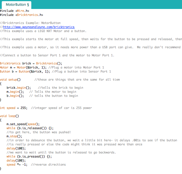
Then we needed to use the "motor button" sketch. This sketch makes the car travel in a straight line until the touch sensor gets pressed, then the car will move in the reverse direction. There is a section in the sketch where the car stops for .01 of a second. This is to debounce the button. It does this to make sure the button really got pressed down. Otherwise the code might think the button was pushed down more than once.
After, Paige and I needed to rewrite the code so that the sciborg would travel forward until it hits a wall, then it would back up and turn a bit, then continue on it's way.
Video
In order to optimize the code, we needed to adjust the time the car would turn for to make sure it didn't turn a large amount. We only wanted the sciborg to turn about 90 degrees so it could explore the room. We also put the sensor on the sciborg with legos. However, the legos were very unstable and would pop off the sciborg sometimes. It would work better if the sensor was permanently attached to the sciborg. It would also be helpful to change the code so the sciborg moves in a straight line as it moves around.
Sunday, March 8, 2015
Arduino Project 1
On tuesday we started a new unit, Feedback and Control. To start we needed to use an Arduino to make a LED flash. The first step was to make the circuit.


We then used the BLINK program using the INTERVAL function instead of the DELAY function. The INTERVAL function would allow us to have multiple LEDs going at different intervals of time. We then needed to change the BLINK WITHOUT DELAY function to work with 4 LEDs and make them flash in a cool pattern


Thought it doesn't show it in the picture, one side of the LED was connected to Pin 13 and the other side was connected to the resistor and then the ground. We then had to upload the program, BLINK onto the Arduino and play the program.
It worked!! We then had to change the program to make a cool pattern with one LED.
We had to make the BLINK function work without any delays. When this happened, it looked like the LED was always on. This is because the LED was turning on and off too fast for any human eye to see.
Our next task was to wire the breadboard with 4 LEDs.
Like the one with 1 LED, all of the lights are hooked up to a pin on the Arduino. The other side of the LED is hooked up to a resistor and the ground. We then had to make the LEDs light up in a cool pattern using the Blink program with the DELAY function. The DELAY function has to go through the amount of time given before it will move on to any other commands.
Our program had LEDs 2 and 4 turn on for 1 second. Then LED 2 turned off and LED 12 turned on for 1 second. Then LED 4 turned off and LED 8 turned on for 1 second. After that, LED 8 turned off. The pattern would then repeat itself over and over.
Each LED in our breadboard blinked at a different interval. We had LED 2 blink at 1 second on, 1 second off. LED 4 blinked at 2 seconds off, 2 seconds off. LED 8 blinked at half a second on, half a second off. LED 12 blinked at 1.5 seconds on, 1.5 seconds off.
That concluded our class on Tuesday. On Friday everyone showed their cool pattern in class and then Professor Banzaert showed us a new mechanism, a servo motor. The programs Sweep and Knob control the servo motor in different ways. Sweep makes the motor move back and forth 180 degrees in steps of 1 degree every 15 milliseconds.
We had to look at the program, understand it, and then change its behavior. We changed it so when the motor was going from 0 to 180 degrees, it would go in steps of 20 degrees every second. When the motor was going from 180 to 0 degrees, it would go in steps of 10 degrees every 150 milliseconds.
Knob controls the position of the servo motor with a potentiometer. The potentiometer had a knob on it that you could turn. Turning the knob 1023 degrees would turn the motor 180 degrees.
We had to look at the program, understand it, and then modify it so it could control the rate at which a LED turned on and off. We had to change from a servo to an LED. We made it so when the potentiometer was at 1023 degrees, the light would blink for 2 seconds on and then 2 seconds off. The rate at which it blinked got faster when the potentiometer went to 0 degrees
Summary
I found it was very important to understand the program before you try to change it. Breaking the program down line by line helps me to understand the syntax. I also found it was important to use the proper brackets or parenthesis. At first we couldn't get the blink without delay program to make 4 LEDs blink in a cool pattern. Later we found out that it was because we didn't put brackets around each of the terms
Monday, March 2, 2015
Lego Racer
Hello those reading my blog! My assignment this week was to make a Lego RACE CAR! My partner, Brooke, and I needed to design a Lego car that could carry a 1kg weight as fast as possible on a 4 meter course. On Friday, our team pitted our car against the cars of everyone else in the class.
We could only use a motor that didn't have internal gearing. This meant that we needed to design a car with gears that went from smaller gears to larger gears to increase the torque of the motor. This
would allow the car to hold more weight. The hardest part of the whole endeavor was getting different gears and Lego pieces to fit in the right way.
The first iteration of the Lego Racer.
When I made the first car, I was mostly seeing how different pieces fit together. I found it difficult to get everything on the car without the wheel hitting the gear and making sure all the gears would work together. However, when I tried to turn on the engine, nothing would move. The is because my gear ratio was too small- 8.33:1. In two places, I had the same gear coupled with one another that did not increase my gear ratio. Those gears were also providing another source of friction, which would make it harder for the car to move. I also noticed that since the car was quite long, it was very unstable. I would need to make it shorter to make it sturdier. So I moved on to a second iteration.
The second time I made the car, I tried to cut down on the number of gears to decrease the amount of friction between the gears. However, only one gear was decreased from the car. I also added a smaller gear to the motor to increase the gear ratio and create more torque. Since I had one less gear in the middle of the car, the size of the car was decreased to make it sturdier. Though, even with the decrease in length, the car was still very unsturdy. This iteration was an improvement from the first iteration because all of the gears would turn and the car would move when I turned it on. However, when I added the 1kg weight to the car, it did not have enough torque to move the car. So Brooke and I moved on to the third iteration.
 |
For our next iteration, Brooke and I changed the design of the car, instead of modifying it like I did in the second iteration. We made the car smaller in width and shorter in length to increase the sturdiness of the car. We also added bigger wheels to the ones connected to the motor and smaller wheels to the ones in back that just rolled. The bigger wheels in back would increase the speed of the car and the gear ratio. We also thought hard on the gear ratio and ended up with a gear ration of 20.83. We made sure that the gear ratio was increased every time gears were paired together. When we tried this car out we found out that it worked! It made the 4 meter course in the 9 second mark.
After we finished this racer, Brooke thought we could increase the torque by adding a smaller gear to the motor and increase the gear ratio. However, when we tried this, the racer went slower than the last iteration. (Unfortunately we forgot to get a picture of this.) So we went back to our third iteration and made it our final RACE CAR!!!
We then raced all the cars to see which car would be the fastest.
Time(s) Gear Reduction
8.42 15:1
We then raced all the cars to see which car would be the fastest.
Time(s) Gear Reduction
8.42 15:1
8.92 22.5:1
9.63 15.6:1
9.68 20.83:1- Our Car!
10.57 24.7:1
10.93 20.83:1
Our car wasn't the fastest, but it still made a good showing and was very close to the car ahead of ours.
9.63 15.6:1
9.68 20.83:1- Our Car!
10.57 24.7:1
10.93 20.83:1
Our car wasn't the fastest, but it still made a good showing and was very close to the car ahead of ours.
Videos

Engineering Analysis
The goal of the car was to create the optimal balance between the torque of the motor and the speed of the motor. The graph below shows the torque vs speed curve of a perfect D.C motor. The motor we used started out with maximum speed, but no torque. This would allow the car to move very fast, but doesn't allow it to hold any weight. The more gears added, the more torque the motor will have. If a million gears were added to the motor, the car would be able to hold a large amount of weight, but the car would move extremely slowly. Our goal was to put enough gears on the car to get equal torque and speed for the car. Our final gear ratio was 20.83:1. We had a 24 tooth gear attached to the motor and a 40 tooth gear. That gear was connected by an axle to a 16 tooth gear which was attached to a 40 tooth gear. That gear was connected by an axle to an 8 tooth gear which was connected to a 40 tooth gear. The gear was connected by an axle to the wheels. (40/24)*(40/16)*(40/8)= 20.83:1 gear ratio.
It is important to note that the gear reduction was calculated without considering the size of the wheels. Since the wheels are connected to the axle and the other gears, they influence the gear ratio of the whole car. A larger wheel would increase the velocity of the car. That is why we changed the wheels attached to the gear in the final iteration of our car.
Another design element of the car was where the wheels were placed in relation to the rest of the car. Since the axles where made out of plastic, the further the wheels were placed from the car, the more the axle would bend. In order to have the weight of the car not be solely on the axle, the wheels would need to be closer to the car. While we tried to have the wheels as close to the car as possible, the gears would interfere with the wheel. Therefore it was necessary to space the wheels further apart than we would have liked and caused some bending in the axle.
Summary
In the end I learned about gear trains and how they influence the torque of a motor. I also learned that there is a lot to consider when making a product because the size and shape of the materials used need to influence the design of the product. I found the hardest part of making the Lego racer was making sure the gears fit together correctly. If I could improve on my design, I would try to make the gear reduction closer to 15:1 to increase the speed of the car. I would also experiment with different wheels if possible.
The goal of the car was to create the optimal balance between the torque of the motor and the speed of the motor. The graph below shows the torque vs speed curve of a perfect D.C motor. The motor we used started out with maximum speed, but no torque. This would allow the car to move very fast, but doesn't allow it to hold any weight. The more gears added, the more torque the motor will have. If a million gears were added to the motor, the car would be able to hold a large amount of weight, but the car would move extremely slowly. Our goal was to put enough gears on the car to get equal torque and speed for the car. Our final gear ratio was 20.83:1. We had a 24 tooth gear attached to the motor and a 40 tooth gear. That gear was connected by an axle to a 16 tooth gear which was attached to a 40 tooth gear. That gear was connected by an axle to an 8 tooth gear which was connected to a 40 tooth gear. The gear was connected by an axle to the wheels. (40/24)*(40/16)*(40/8)= 20.83:1 gear ratio.
It is important to note that the gear reduction was calculated without considering the size of the wheels. Since the wheels are connected to the axle and the other gears, they influence the gear ratio of the whole car. A larger wheel would increase the velocity of the car. That is why we changed the wheels attached to the gear in the final iteration of our car.
 |
| http://lancet.mit.edu/motors/colorTS1.jpg |
Summary
In the end I learned about gear trains and how they influence the torque of a motor. I also learned that there is a lot to consider when making a product because the size and shape of the materials used need to influence the design of the product. I found the hardest part of making the Lego racer was making sure the gears fit together correctly. If I could improve on my design, I would try to make the gear reduction closer to 15:1 to increase the speed of the car. I would also experiment with different wheels if possible.
Subscribe to:
Posts (Atom)