Thursday, May 14, 2015

Final Project Part 6

Final Project

Description:

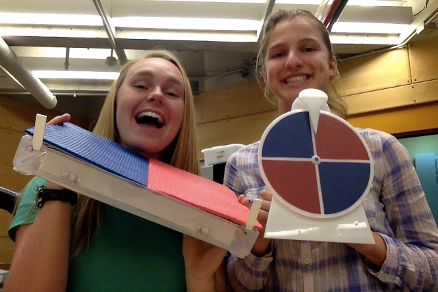
We made a mat for children that would be inviting for children so that they will hopefully leave their fun activity to go to group time. The teacher will turn the spinner to one of the colors and tell the children what side of the mat to sit on. The children will come and sit on the side of the mat indicated by the spinner. The LED on that side of the mat will flash in a pattern as a reward for sitting on that side of the mat. The mat then turns off for the rest of group time as to not be a distraction to the children during the lesson.

Highlights from Past Blog Posts

  • 1st Visit: The class visited the CSC to observe and find some common needs of the children that we could make a project to help them with
  • Brainstorming: We drew up many different ideas of mats that we could make to help the children in their transition from play time to group time.
  • 2nd Visit: Izzy met with the director of the CSC to go over our initial idea and observe the children at group time.
  • Mock-Up: We created our initial idea out of foam core as a visual example of what our project will look like
  • Building: We made the spinner and some pieces of the mat out of delrin and assembled the mat.
  • Code: We wrote the code for the LEDs to turn on when the button was pressed.
  • Presentation: We showed off our lovely mat to the class and visitors.
Clip of Working Device


Final Device
Outside View

View with Flaps Opened

Team Time


Improvements 

If we had more time we would...
  1. Make the mat thinner, lighter and easier to handle by children. Possibly adding a handle.
  2. Make the LEDs brighter so the children can see the pattern better.
  3. Make the LEDs flush to the mat so the children can't damage them.
  4. Make sure all the wires were hidden from the children.
  5. Make the mats sealable so the children can't get to the wiring, but it can still be accessed in case anything goes wrong.
  6. Make the spinner and mat colors the same.
  7. Other improvements can be found in the posts Final Project Part 5 and 4.
Final Thoughts

In the end, I loved how our design looked. It was very clean and visually pleasing. I especially liked the hinges we added to the mat because they made it easy to get in and out of the workings of the mat. With some further adjustments, it could be used in the classroom. I like how we combined all of the knowledge we learned this semester in the final project. I loved seeing how the information we gained in the classroom could be used to help actual people.


Final Project Part 5

The Code

Make a code that turns the LED on the blue side of the mat when the children sit on the blue mat and turns on the LED on the red side of the mat when the children sit on the red mat.

Beginning Steps

Before we started writing the code, we looked at some past code that was similar to what we wanted to write. We looked at the SOS code because it included functions we wanted to implement in our final code.


Code Part 1:

Our initial code read the state of the button. If the both buttons on one side of the mat were pressed, then the LED on that side would turn on for two seconds and off for one second. The same would happen if both the buttons were pressed on the other side of the mat. If the buttons were not pressed, the LED would be off. The LED turned off for a short time in this code because we wanted to make sure the code was functioning like we wanted. If the mat were implemented in a real classroom, the LED would turn off for 10-15 minutes, about the time of a typical group time. This way the mat would not be a distraction for the children when they are supposed to be listening to the teacher

Final Code:
We changed the code so that the LEDS would blink in a pattern, instead of only turning on when the buttons are pressed. We thought this would make the mats a bit more exciting and get the children to go to group time.  The short1, short2, long1, and long2, functions show the amount of time the led would be on and then off. Short1 and short2 turn the LED on for half a second and then off for half a second. Long1 and long2 turn the LED on for 1 second and off for half a second. Putting them in sequence in the if statement creates a pattern for the LED. The numbers 1 and 2 correspond to the LEDs on either side of the mat. We wrote the code this way so that it would be easy to change the pattern if someone wanted.


Improvements

1) Make the time the light is turned off longer so it won't interrupt group time.
2) Change the code so when one side of the mat is pressed, the other side can't turn on at all. At this time, if both sides of the mat are pressed at the same time, the lights will alternate turning on after the delay has passed. However, if it was actually implemented, the delay would be much longer and this would not be an issue.
3)Change the code so only one button on one side of the mat needs to be pressed down for the light to go off. At this time, both of the lights on one side need to be pressed down.

Reflection

I had a lot of fun playing around with the code. It was simpler than some of the code I did in the past. It worked really well!

Final Project Part 4


Building Physical Materials

Making of the mat and spinner!

First Steps:
Before cutting any delrin, Izzy first created test pieces to make sure all of the our attachments would fit together snugly. Once we knew what sizes to make our holes, we were ready to design our project.

Beautiful Test Piece

Peg for Test Piece


The Mat:
The base of the mat was made out of a plastic box that we cut the bottom off. Larry helped us cut the box to the proper size.
Uncut Box


Cut Box

 Our arduino, battery pack, and bread boards were mounted on those. To keep the fragile arduino safe from the weight of the children, we constructed a box out of delrin to house all of our components. We had small holes on the top part of the delrin box for the buttons to live so that they could be depressed by the children sitting on the mat. We also cut access holes over where the breadboards lie to make them more accessible in case the wires need to be adjusted. For additional easy access to the wires, we hinged the delrin box to the plastic box.
Top of Delrin Box Solidworks 

Side of Delrin Box Solidworks
Cutout Piece of Delrin (for the top of the box)

Hinges 

Complete Delrin Box

We then mounted the yoga mats with the top of the plastic bin. It helped to create a firmer base for the children to sit on. We hinged either side of the mats to the plastic bin to create easy access inside the mat. Izzy added Popsicle sticks on the inside portions of the mat to give it more weight.


Gluing mats to the plastic

Then we soldered all of our parts to sensors to longer wires so they would connect to the breadboard. After that, we wired the mat together. This proved to be complicated because the wires weren't long enough to stay in their spots when we lifted the delrin box. Wires kept coming out of where they were supposed to be and it was difficult to keep putting them back where they belong. We eventually got everything in the right places. We also needed to tape the buttons to the delrin box so that they would face the right way.

Side View of Wires 
Inside the flaps

The Spinner:

We wanted a spinner for the children so that they could have a visual reminder of where they were supposed to be on the mat. We decided against pegs on our spinner and instead let the spinner slow down due to air resistance because it simplified the design. We could add carpet or another type of material to the spinner if it still spins too fast. Pictures of each part of the spinner are featured below.


Spinner Arrow

Spinner

Side Support

Back Support
We cut Vinyl to make the colorful sections of the spinner.

Stencil for Vinyl Sections

FINISHED PRODUCT!!!!

Spinner in Action!
Beautiful

Spinner and Box, side by side.

Reflection:

It was wonderful to see the mat come together and start to look like a final product. We needed a lot of help from Larry to cut the box and put on the hinges and make sure they didn't interfere with the insides of the box. However,  I would make some changes if I did it again. I would have made the wires longer so that the delrin box could be opened all the way without pulling the wires out. I would also make the vinyl pieces on the spinner and the yoga mats the exact same color. In the end, though, I think the mat and spinner ended up looking great!


Wednesday, May 13, 2015

Final Project Part 3


Foam Core Mock-Up
We needed to create a mock-up of our idea to show the class and Professor Banzaert.


Fig 1 Spinner and Mat Outside
Fig 2 Underside of Top Mat


Fig 3 Side View of Spinner
Fig 4 Between the Bottom and Top Mat


Layers of Mat
  1. The bottom layer of the mat and what the arduino would sit on (Fig 4) would be a stiff material, either wood or delrin.
  2. Next (Fig 4) would be the wires, the push button sensors, the arduino, and the battery pack.
  3. A stiffer material (Fig 2), or either wood or delrin, would go on top so that the sensors  would have something stiff to respond to. This layer would have two sections, a red side and a blue side, so that only the buttons to one side would be pressed.
  4. A yoga mat (Fig 1) would be the top layer of the mat with the LEDs connected to the mat so the children could see them.
The Spinner (Fig 1 and Fig 3)
  1. The spinner would be made of either delrin or wood.
  2. It would have a sensor to tell what color it landed on.
  3. There would be pegs in the round part of the spinner (tacks in mockup) that would hit a rubber flap to slow down the spinner and make sure it doesn't turn forever.
  4. The piece to communicate with the mats would be connected to the back of the spinner (not shown).
Adjustments
Due to time constraints, we needed to simplify our idea. Since we have not worked with wireless communicators before, we needed to cut that part our of our plan. Instead the mat and the spinner will work separately. The teacher will tell the children what side of the mat to sit on, and when the children sit on the mat, the section they sit on will light up. If the child moves to the other section of the mat, that will light up. The code will only allow one side to light up during a session.

Major Decision
We talked about what we should make the actual mat out of. We tried looking up trays on the internet, but they were too expensive. We contemplated using a 5 gallon bucket, but it wasn't big enough for what we need. We even considered using a trash can but that would be too difficult to cut. We decided to use a plastic box and lid that we have in the lab as our mat. We will cut the box at the bottom to make it the proper size of the mat. The lid will be cut and used as the stiff material connected to the yoga mats.

List of Materials
  • yoga mats (1 red, 1 blue)
  • plastic bin and plastic lid 
  • arduino board
  • 2 LED light tags
  • small button sensors
LED Light

Push Buttons

Yoga Mats

Next Steps
Create the code, spinner and mat for real.


Final Project Part 2

Classroom Visit
Izzy visited the classroom to make sure the idea would be useful in the classroom and to get tips on how to improve the idea.

She went with a storyboard on the mat.

Suggestions:
  1. The main goal of the mat should be to get the children to sit on the mat at the start of group time, and not to remind them to stay on the mat. It would be too distracting for the children to have lights going off in the middle of group time.
  2. The mats should be no wider than 16.5 inches to make sure the mats will fit in the group time circle. 
  3. Red and Blue or Black and White are the best colors to use for the mats. They are some of the first colors that the children recognize
  4. The mats should be easily able to stack and distribute.
  5. The color wheel should not be distracting to the children. The teacher should be able to turn the wheel calmly if needed.
Next Steps
We need to integrate the suggestions into our idea and create a mockup of it to show the class.

Final Project Part 1

Brainstorming Session

Objective:
Our goal is to create a mat that the children will want to sit on when it is group time. If group time happens after playtime, children often do not want to leave their fun activity to come to group. They try to finish what they are doing or wash their hands for a long amount of time. We want to create a mat that is fun for the children so they want to sit on the mat at the start of group time.

Ideas


1) Create a mat with four color sections. The teacher would control with part/color the mat would respond to. Once the child sat on the mat, a sensor would be depressed that would make a light would turn on in the mat so the children know that they sat on the right section. The children would need to sit on a mat the teacher chooses. This would make sitting on the mat a game for the children and they would want to sit on the mat.
   Possible Problems: The mat would be too big for the classroom. If the teacher had a controller that      controlled all of the mats, there would be a lot of wires involved that could be a hazard to the              children. Also, there would be no visual cue to remind the children where to sit which could lead to    confusion.

2) New Edited Idea: Create a mat with only two sections to conserve space. To have less wires, my partner and I would try to find a wireless way for the mat and the sensor the teacher has to communicate. We would also create a large spinner wheel to act as a visual for the children to look at. A sensor would be attached to the spinner that could sense what color the arrow is pointing to.

Brainstorming Mat Sensors
  1. Light Sensor: A light sensor would sense if the child was sitting or not based on the amount of light that reaches the sensor. When a child sits on the mat and covers the sensor, the sensor would read dark. The largest problem with this idea is that the light sensor would need to poke out of the top of the mat and could be very uncomfortable for the children to sit on. Another problem is that the child would need to be sitting directly on top of the sensor for it to work. If the child was sitting on the side of the mat, it would not register.
  2. Weight Sensor: A weight sensor would be able to detect the weight of the child. The benefit of this sensor is that the child could be sitting on any part of the mat and the sensor would be able to pick it up. The problem with this idea is that weight sensors could be expensive to buy.
  3. Button Sensor: A button sensor senses if the button is pushed or not. There would be multiple button sensors under the mat, so no matter where the child sat on the mat, the sensor would be able to tell that a child was on the mat. A possible problem would be that it could be uncomfortable for the child to sit on. To make it more comfortable and stable, we could add a layer of stiff material above the buttons.

     Ultimately, we decided on the button sensor due to cost restrictions and because the varied                  weights of the children would make it difficult to program the sensor.


Brainstorming Spinner Sensors
  1. Color Sensor: It would be able to tell if the spinner was on red or blue.
  2. Light Sensor: Since blue is a much darker color than red, the light sensor could tell a difference when it landed on red or blue


Further Steps
Our next steps are to observe group time and to go over our ideas with the director at the CSC and hear her input as well as asking some questions.


Sunday, May 10, 2015

Sciborg Line Following

For the last project with the Sciborg, Paige and I needed to get our Sciborg to follow a line of white tape on a piece of darker wood. We used a light sensor to tell the difference between the light tape and the dark wood. We ran into many difficulties along the way.

Bang Bang Control
For the first part of the project, we needed to use bang bang control to make the Sciborg follow the sensor. We started by trying to make the light sensor read the the middle of the tape. However, this only allowed the Sciborg to turn in one direction and would result in the Sciborg moving in circles when it got to turn instead of following the line. After talking with a fellow student, however, we learned that the Sciborg should follow the edge of the line instead. This way, the Sciborg could turn right when it read a very light reading or left when it read a dark reading. This allowed for more control of the Sciborg.


Proportional Control
Our second objective was to get the Sciborg to follow the line using proportional control. Our sciborg can be a bit finicky and won't move at a certain range of power. Because of this, we need to add extra lines of code to make sure the Sciborg doesn't hit that range. The next problem we ran into was the speed of the Sciborg. When we first made the code, the Sciborg would move faster than it could read the light. This would cause the Sciborg to spin wildly instead of following the line. However, after changing the gain and limits, the Sciborg followed the line.


Reflection
Making the code in arduino was very aggravating because it took a long time to make the code work like it should. However, it was rewarding once the code actually worked. Overall, I liked working with arduinos and I feel that I know the language pretty well now. 


Tuesday, April 14, 2015

Matlab 2


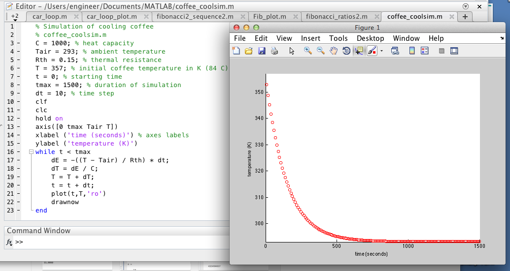
To further our understanding about MATLAB, we had to show a code that simulates how a cup of coffee cools to room temperature. The code and resulting graph. The graph plots time on the x axis and the temperature of the coffee on the y axis. Note all temperature is in Kelvin.

Question 1: How does the cooling behavior change if we vary the parameters Rth (thermal resistance) and C (heat capacity)?

 If you increase Rth and C, the coffee will retain more heat and the graph will decrease slower and the coffee will stay hot longer.
Rth increased from .8 to 2.85 while C stayed the same.

Rth stayed the same, while C increased from 1000 to 2000
Rth increased from .85 to 2.85 and C increased from 1000 to 2000
On the other hand, if C and Rth decrease, the coffee will not retain heat as well and the coffee will cool off much quicker.
Rth decreased from .85 to .15 while C stayed the same

Rth stayed the same, while C decreased from 1000 to 100

Rth decreased from .85 to .15 while C decreased from 1000 to 100

Then we needed to add a heater to the coffee. If the coffee started at room temperature and turn the heating element on, the element would add thermal energy to the system at a constant rate P.

Question 2: Calculate the value for P if we want our coffee to heat up to the Starbucks ideal of 84 degrees Celsius or 357 Kelvin?

P=75.29- We were given an equation in class and we then solved it to find this number

Once we found P, we needed to incorporate P into our program to see how it would affect the system. Over time, the coffee heated up to the desired temperature.


Then, we needed to modify the program to simulate a temperature controller that uses bang-bang control to reach and maintain the desired temperature.


Below is a zoomed in version of the graph.

Page 9. Question 1: Why is bang-bang control appropriate for many thermal systems? When might it be insufficient?

It is appropriate for thermal systems because it heats up to the desired temperature as fast as possible and is also cheap and easy to implement. The reason why our proportional control heated up faster than our bang bang control was because the max power in our proportional control is a lot larger than our max power in our bang bang control. However, it could be insufficient if it would be detrimental if the temperature went above the desired temperature as bang-bang control will ends up going a small amount over the desired temperature.  

Then we needed to create a program that uses proportional control to reach and maintain the desired temperature.


Page 9. Question 2: How does this approach compare to bang-bang?

This approach never reaches the desired value, though it does get very close.

After, we assumed that there was a delay between the time the coffee reaches a given temperature and when the temperature sensor records that temperature. We needed to modify both of of our programs to include the affect of adding a "sensor delay".

Bang Bang Control
The impact of the sensor delay is that the temperature gets read 5 seconds after it was initially read. Because of the delay, the first 5 seconds of the graph show a temperature of 293. It also doesn't turn the power on as often since it records temperature of the coffee 5 seconds after it reads the temperature.

Proportional Delay

The sensor delay has the effect that the temperature gets recorded 5 seconds after it was initially read. Therefore, the first 5 seconds of the graph are at a temperature of 293. The temperature also goes over the desired temperature since it records the temperature 5 seconds after it has read it. Then the system will turn off the power after it has gone over the desired temperature by 5 seconds.

Question2: What other delay(s) might you expect in your thermodynamic system, apart from sensor delays? 

One other delay can be an action delay. There could be a delay when the power is supposed to turn on to when it actually turns on.

Reflection:
I completely understand bang bang and proportional control now. It took us a long time to do the last problem with the delay because of small syntax errors. So I know that it is important reread the code to fix all errors.